

A closer look at inductors and chokes In EVs
Traction motors and transformers are the magnetic components that seem to get all the attention, but the humble inductor/choke is just as critical a component in modern power converters, and it has surprisingly profound effects on performance, reliability and cost. Another temptation for the bewildered design engineer (or one that is just short on time—but isn’t that all of us?) is that there are numerous inductors/chokes available COTS (Commercially Off The Shelf), which is generally not the case for transformers, and choosing a COTS part isn’t necessarily a bad option—specialist suppliers offer very high-quality magnetic components, and possibly for much less than a bespoke component, even in production quantities.
The humble inductor/choke is a critical component in modern power converters, and it has surprisingly profound effects on performance, reliability and cost.
However, that doesn’t absolve the design engineer from verifying the suitability of a COTS component in a given application, as the last thing you want is for a component you barely vetted to become an occult source of inefficiency, unreliability, or that most dreaded of outcomes: to cause the device to fail Electromagnetic Compatibility Compliance (EMC) testing.
While a choke is technically a specific type of inductor (one that can handle significant DC bias before fully saturating), the term is frequently abused (e.g. the “common mode choke” found in pretty much all AC mains filters never sees DC, so it is not a choke). Therefore, it’s probably best to treat the terms inductor and choke as interchangeable. That said, inductors are broadly used for three major functions in EVs: in conventional low-pass LC filter networks for producing (reasonably) clean DC outputs in switchmode power converters; in tuned (aka resonant) LC networks, either in explicitly-resonant converter topologies, or just to reduce losses during the switching transitions in PWM topologies (aka quasi-resonant or soft-switching); and in EMI filters for blocking the emission (or reception) of radio-frequency noise.
These applications place very different demands on inductors, hence the earlier admonition that just because you can get one COTS doesn’t necessarily mean it will work all that well in the specific part of the circuit you’ve dropped it into.
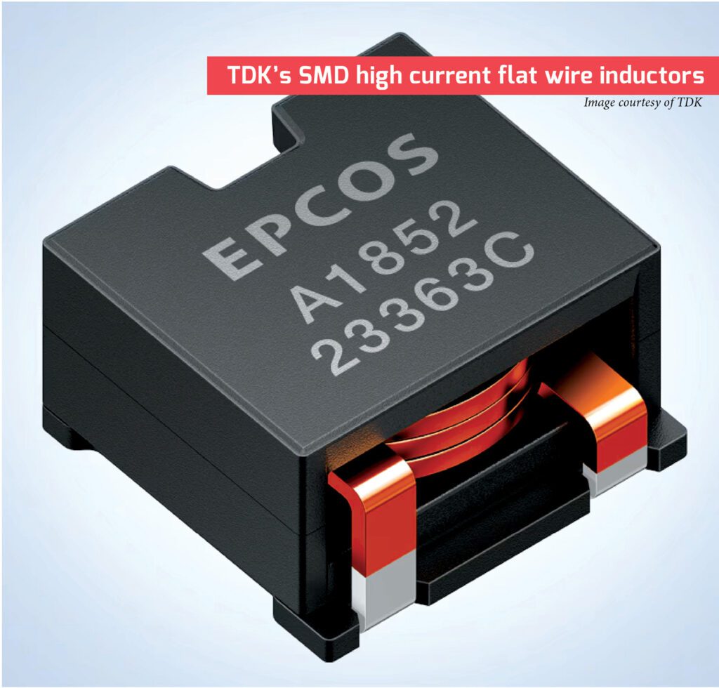
The edgewound flat wire construction is preferred at higher current ratings, especially at moderate switching frequencies under 150 kHz.
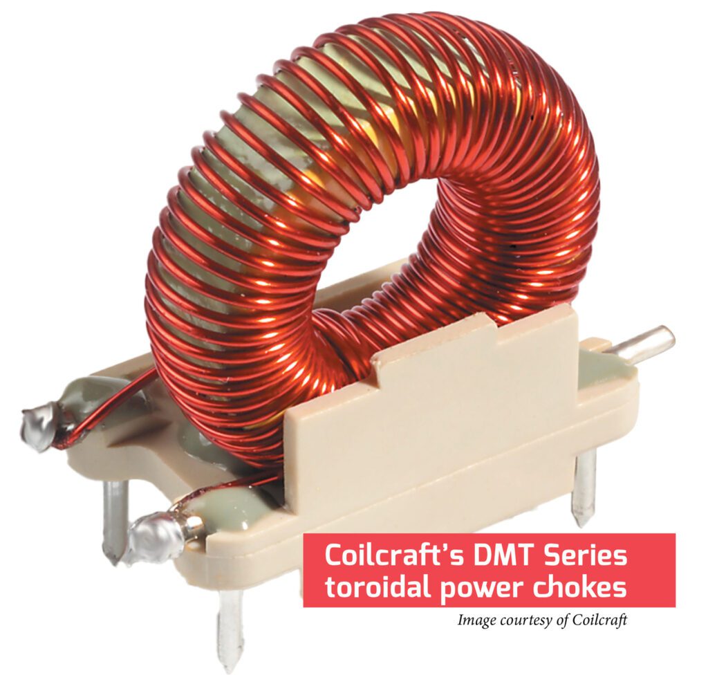
The vast majority of inductors used in power converters, regardless of topology, will have a ferromagnetic core—that is, not be a simple coil of wire—and most of the time that core will be in a shape such that the magnetic flux from the windings can follow a completely closed loop (a toroid is the classic example here). The latter feature might not be necessary for the functioning of the circuit, but it is key if you want to pass EMC compliance testing, because any flux lines that don’t escape the core are bound to cause noise issues elsewhere.
For example, the now-ubiquitous drum-core SMT inductors that might look ideal for use in low-power auxiliary converters don’t have a closed magnetic loop—the flux lines must pass through air to complete their circuit—which can turn these little devils into miniature “EMI cannons” (an actual sobriquet I’ve heard used to describe them). Choosing a core shape that closes the flux loop is only part of the battle, though, as other parameters and design goals are often mutually exclusive, so compromise is inevitable. For example, core materials that are optimized for low AC losses (hysteresis and eddy) tend to have a lower saturation flux density, so will require more core area for a given inductance and power handling ability, which in turn increases the amount of stray capacitance, and so on.
The main function of the series inductor in an LC output filter is to reduce the amount of AC ripple seen by the shunt capacitor that follows it without also being overwhelmed by the DC flowing through it. This increases the importance of minimizing the DC losses of the windings over the AC losses of the same, and of the core.
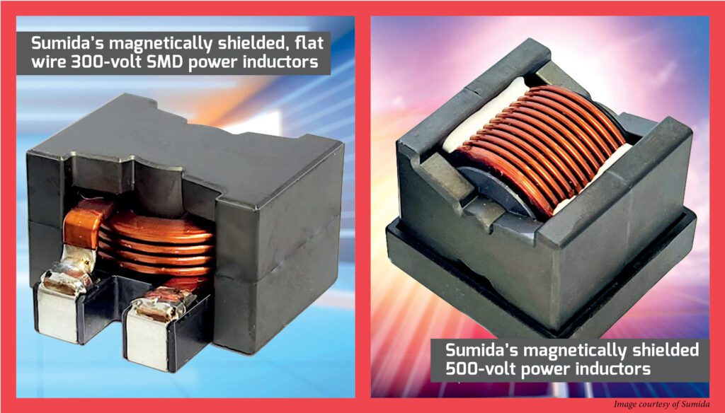
A single layer of conventional magnet wire (using multiple strands in parallel if necessary to achieve the target current rating) will typically work well. Also possible (at the expense of higher stray capacitance) is the edgewound flat wire construction—this type is preferred at higher current ratings, especially at moderate switching frequencies (under 150 kHz), though it tends to have a higher stray capacitance. As for the core itself, almost any “power material” will work here (as opposed to materials optimized for RF/tuned circuits or, worse, EMI filters), as long as there is either an explicit or distributed air gap to prevent saturation from the DC bias.
The gap is explicit (i.e. a literal gap) in ferrite cores, and cores with standard gap lengths are available COTS from most manufacturers, though there is little penalty in specifying a custom gap as long as you buy enough of them, and can wait to have them machined, as it takes diamond tooling to cut ferrite. Note, however, that a discrete gap will be a potent emitter of EMI, so it will almost certainly need to be shielded by the windings (at the cost of increased AC losses in them), hence the gap is almost always cut into the center leg of (for example) pot- or E-shaped cores; shimming the core halves might be fine for prototyping, but not for production.
Cores using a mix of powdered metal and a binder typically have a distributed gap which can be adjusted by the manufacturer by varying the ratio of the two. As with ferrites, there are several standard gaps available (specified indirectly via the permeability), though here there is a much higher cost penalty for custom values, so one is strongly advised to stick with the standard offerings.
Inductors used in tuned (resonant) LC networks aren’t subjected to any DC bias, but are typically operated at much higher frequencies, that being one of the main goals of resonant (or quasi-resonant) operation, after all. Consequently, rather more emphasis is placed on minimizing the AC losses in both the core and the windings over simply minimizing the winding resistance, but with one major caveat: the circulating current in a fully-resonant converter operating near resonance will be considerably higher than the actual load current (several times higher, perhaps), so winding resistance shouldn’t be completely ignored.
Eddy current losses are a function of both core material and its construction—a higher bulk resistivity and a minimally thick dimension help the most.
The core losses are the result of hysteresis, or the effort expended in flipping the magnetic domains back and forth, and eddy currents, which arise from currents being induced into the core normal to the magnetic flux path. Hysteresis losses are entirely a function of the core material. Ferrite and low-mix powdered iron perform the best, as molypermalloy powder (MPP) and other powdered metal mixes trade higher losses for a higher permeability value and saturation flux density.
Eddy current losses are a function of both core material and its construction—a higher bulk resistivity and a minimally thick dimension help the most. Of course, the lowest core losses result from having no core at all, and this might very well be an option at frequencies above 500 kHz or so, though if you don’t want this inductor to be an EMI cannon then it would still be best to make it toroidal in shape.
The winding construction for resonant inductors is rather more difficult to optimize from a losses-vs-costs perspective, because the common and low-cost technique of twisting together several smaller magnet wires to get the necessary current rating might not perform nearly so well in a resonant application due to skin and proximity effects. Skin effect is a phenomenon in which eddy currents induced into a wire by the very high-frequency current it is carrying force said current into a ring, with no current flowing in the center, and this effect scales with the square root of frequency and the square of the diameter. For example, the maximum frequency a #18 AWG wire (~1 mm diameter) can carry before skin depth starts to affect it is ~17 kHz, and this drops to a mere ~4.2 kHz for #12 AWG (~2 mm diameter).
A huge number of strands will be needed to minimize skin effect losses above 200 kHz or so, but unless each strand spends the same amount of time (so to speak) facing the core and the wiring surface, proximity effect starts to dominate the losses (this is basically skin effect arising from the magnetic fields from adjacent winding layers). Both skin and proximity effects can be alleviated with Litz wire, which consists of many (up to hundreds!) of individually insulated strands that are woven in such a way that each of them continually changes its position between the center and the perimeter of the wire.
There are practical limits to how far this concept can be taken, however, as the cost of Litz goes up with strand/bundle count, while the individual strands will become too small to withstand the weaving and bundling process at some point (the usual cutoff is around #44 AWG). There are also more subtle reasons to keep the strand count down, such as an increasing ratio of insulation to copper, and the fact that proximity effect happens between each strand and each bundle of strands (albeit not to the same degree as between actual winding layers).
The upshot of all this is that it will often be more economical overall to go up a step or two in core size just to reduce the number of turns required to achieve the target inductance, and especially to keep all the turns in one layer (which also dramatically reduces the stray capacitance of the winding). Even so, operation at >200 kHz or so will almost certainly require Litz, so budget for that cost increase accordingly.
It will often be more economical overall to go up a step or two in core size just to reduce the number of turns required to achieve the target inductance, and especially to keep all the turns in one layer—which also dramatically reduces the stray capacitance of the winding.
The final application for inductors is EMI/noise filtering, and here high AC losses in both the winding and core are more of a feature than a bug, and going with a COTS component might be the best choice. If you are rolling your own—or just to better select a COTS component—then minimizing the stray capacitance of the winding is a relatively higher priority than anything else, as this capacitance is a prime vector for high-frequency noise to bypass the inductor, defeating its very purpose.
A single layer winding with a single magnet wire of appropriate gauge for the current is the preferred construction here. If the EMI filter inductor will have to carry considerable DC or low-frequency (i.e. mains) AC current for its size—and this could be on the order of a few mA for a signal-level inductor—then the same design guidelines as explained above for DC-biased chokes will apply, though with much more emphasis on employing a closed-form core shape so that these filter chokes doesn’t become impromptu EMI cannons.
RF noise typically manifests on all wires passing through an enclosure, so common-mode filtering will be more effective than individual filters for each power and signal line (i.e. in normal or differential mode). This is most easily achieved by putting all of the windings for a related group of wires—including their ground return—on a single core (e.g. the AC mains power inlet, signal lines to the motor encoder, throttle pot, etc).
The windings will appear in series for common-mode current, but almost disappear for normal-mode current. The latter could be a minor issue in that some inductance may still be desired for differential-mode filtering, in which case purposefully constructing the windings to have high leakage inductance (e.g. by physically separating them) will prove beneficial.
The ubiquitous toroidal common-mode choke found in practically every AC mains filter embodies all of these principles—the toroidal core is a closed form, so it emits almost zero EMI, and the windings consist of a single layer of a single magnet wire wound on opposite sides of the core, resulting in high AC losses, the minimum possible distributed capacitance, and relatively high leakage inductance, with some differential-mode filtering thrown in for free. Most COTS common-mode chokes will already be listed/approved with the relevant safety agencies as well, making them an even more compelling choice over bespoke components.
This article first appeared in Issue 71: January-March 2025 – Subscribe now.
Source link